NBR Insulated Extra Flexible Copper Welding Cable

Construction:
generally conforms to, Based on CENELEC HD 22-6 31, VDE 0282, IEC 245-6, BS 6899, IS 6830/84
Conductor :- High conductivity, bare annealed copper flexible conductor, EC copper class 5 and class 6 generally conforms to IEC 60228, DIN VDE 0281
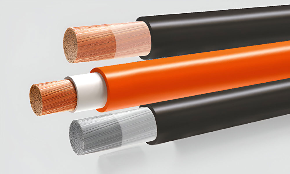
Insulation :- NBR Insulated flexible Nitrile rubber (NBR) insulated
Colour Code :-
Orange & Black Jacket
(*Any other Color on specific
request can also be supplied)
Fixed installation :- -30°C to max. +90°C
Nominal voltage :- 600V
Test voltage :- 2500V
Mechnical Properties :-
Tensile strength = 10 N/mm² Min.
Elongation =
300 Min.
Min. bending radius :- 6 × cable diameter
Flame propagation :- Flame retardant test as per IEC 60332-1
✔ NBR/NBR
- Designed for the secondary (high current) connection to automatic or hand–held metal arc welding electrodes. It is suitable for flexible use under rugged conditions, on assembly lines and conveyor systems, in machine tool and automatically operated line and spot welding machines.
✔ Standard length cable packing:
- Coils 100, 200, 300 and 500 m. in wooden reels
Features:
- Ultra high performance flexible welding lead, double insulated
- Better flame retardant properties
- Excellent flexibility to last longer in flex applications. Based on CENELEC HD 22-6 31, VDE 0282, IEC 245-6, IS 473, BS 638-4
- Outstanding toughness & durability
- High resistance to cuts, tears & abrasion
- Resistance to oil, solvents and chemicals
- Excellent ozone and weather resistant
Current Rating:-
- The maximum current ratings of flexible welding cables for different duty cycles are based on an ambient air temperature of 25ºC and a maximum conductor temperature of 90ºC. The percentage duty cycles for various processes and applications are as follows:
- Automobile Welding: up to 100%
- Semi-automatic Welding: 30% to 85%
- Manual Welding: 0% to 60%
- Very intermittent or Occasional Welding: up to 20%
Voltage Drop:-
- When total cable lengths in excess of 15 mtrs., are involved, it may be necessary to use cables of larger cross section to ensure that the voltage drop is not excessive and welding currents are maintained at adequate levels.
Cross Sectional Area (Sq. mm.) |
Copper Construction (Nos. / Dia. mm) |
Inner Dia (mm) |
Outer Dia Appx. (mm) |
Max. Conductor Resistance at 20°C (Ω/km) |
Current Rating - Welding Application (Duty Cycle) | Non Welding Application (amp) |
||||
---|---|---|---|---|---|---|---|---|---|---|
100% | 85% | 60% | 30% | 20% | ||||||
10 | 322 / 0.20 | 6.30 | 9.90 | 1.910 | 105 | 115 | 135 | 190 | 235 | 110 |
16 | 511 / 0.20 | 8.00 | 10.70 | 1.210 | 135 | 145 | 175 | 245 | 302 | 138 |
25 | 798 / 0.20 | 9.50 | 12.10 | 0.780 | 180 | 195 | 230 | 330 | 402 | 187 |
35 | 1121 / 0.20 | 11.00 | 14.20 | 0.554 | 225 | 245 | 290 | 410 | 503 | 233 |
50 | 1596 / 0.20 | 12.30 | 16.30 | 0.386 | 285 | 310 | 370 | 520 | 637 | 295 |
70 | 2220 / 0.20 | 14.40 | 18.70 | 0.272 | 355 | 385 | 460 | 650 | 794 | 372 |
95 | 1349 / 0.30 | 16.60 | 20.80 | 0.206 | 430 | 475 | 560 | 790 | 961 | 449 |
120 | 608 / 0.50 | 18.20 | 23.00 | 0.161 | 500 | 540 | 650 | 910 | 1118 | 523 |
150 | 760 / 0.50 | 21.10 | 27.60 | 0.129 | 580 | 620 | 740 | 1040 | 1297 | 608 |
185 | 943 / 0.50 | 23.80 | 30.80 | 0.106 | 660 | 715 | 850 | 1200 | 1476 | 690 |
240 | 1225 / 0.50 | 26.80 | 34.40 | 0.0801 | 770 | 830 | 990 | 1350 | 1587 | 744 |
300 | 1498 / 0.50 | 30.30 | 37.50 | 0.0641 | 880 | 950 | 1135 | 1530 | 1790 | 840 |
400 | 2035 / 0.50 | 36.30 | 41.30 | 0.0486 | 925 | 1000 | 1195 | 1690 | 2070 | 970 |
Ambient temperature °C | 20° | 25° | 30° | 35° | 40° | 45° | 50° | 55° | 60° | 65° |
---|---|---|---|---|---|---|---|---|---|---|
Rating Factor | 1.04 | 1.00 | 0.96 | 0.91 | 0.87 | 0.82 | 0.76 | 0.69 | 0.64 | 0.57 |
The number of wires is approximate and wire diameter is nominal; they shall be such as to satisfy the requirements of conductor resistance of IEC 60228 / DIN VDE 0295 / IS 8130 / BS 6360
In view of continuous improvements in our design and process, specifications given here in are subject change without notice.